Taking Custom Design to New Levels
PROUD TO BE PART OF THE BRIN FAMILY OF COMPANIES

OTHER BRIN LOCATIONS
Brin Glass Company | Minneapolis, MN
St. Germain’s Glass | Duluth, MN
Heartland Glass | Waite Park, MN

Robotic systems combine sensors, software, controllers, and mechanical parts to perform tasks with varying levels of autonomy. A factory robot may grip a metal component, follow a programmed path, and adjust its motion using sensor feedback. Its controller interprets instructions; motors and actuators turn them into movement. When sensing, planning, or calibration fails, even a precise machine can miss its target.
The scale is substantial. The International Federation of Robotics reported 4,281,585 industrial robots operating worldwide in 2023, a 10% increase from 2022. Its World Robotics 2024 report also recorded 541,302 new installations that year. These figures show growing adoption, but they do not mean every robot can work independently. Many systems still need careful setup, supervision, and maintenance. That distinction matters.
Robotics pioneer Joseph Engelberger captured a persistent definitional problem: “I can't define a robot, but I know one when I see one.” His remark remains useful because robotic systems range from fixed factory arms to mobile machines that navigate changing spaces. Their shared logic is less mysterious: sense the environment, process information, act, and check the result. Not quite magic. In this guide, we will examine each stage, explain common system types, and show how their components work together. A clean diagram can make the process seem effortless. Real deployments are less tidy; lighting, friction, and unexpected objects can expose design limits. That is worth remembering.
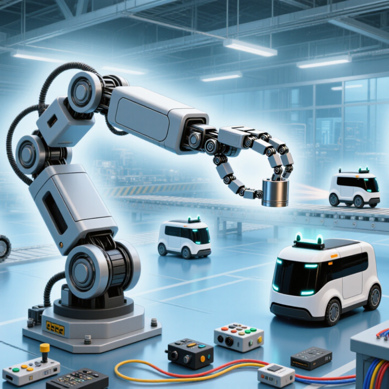
A robotic system combines physical parts, control software, and a way to sense or respond to its surroundings. Its structure supports movement or manipulation; motors, valves, or other actuators create action. Sensors gather information, such as distance, pressure, or joint position. A controller compares those signals with a target and adjusts the action.
Feedback is central. Without it, a machine may repeat a motion but cannot reliably correct for a shifted object or unexpected resistance.
Consider a small robot arm moving a cup. A camera or position sensor helps locate the cup, while motors guide the arm and a gripper closes around it. The controller must coordinate timing and force, then respond if the cup slips.
Not magic.
A robotic system does not need to look human, and it does not need full independence. Some systems follow fixed instructions; others adapt within defined limits. The boundary can be fuzzy: a conveyor with sensors may be automated, yet lack the sensing, decision, and action loop that makes a system meaningfully robotic.
In practice, reliable performance depends on calibration, safe limits, and testing under real conditions. Even a well-designed robot can misread a shiny surface or behave poorly when parts wear.
That matters.
What Are Robotic Systems and How Do They Work?
The Main Components of a Robotic System
A robotic system combines a physical structure, motion hardware, sensors, control software, and a tool suited to its task. The structure supports the robot and sets its reach. Motors and actuators move joints or wheels; a gripper, camera, or welding head performs the work. Sensors measure position, force, distance, or temperature. The controller processes those signals and sends commands to the actuators. Power and communication links keep the components working together. Simple on paper.
The International Federation of Robotics reported 4,281,585 industrial robots in operation worldwide in 2023, with 541,302 new installations that year, in World Robotics 2024. That scale makes component reliability practical, not theoretical: a faulty sensor can stop a production cell, while poor calibration can spoil repeatable movement. In a warehouse, for example, a mobile robot may use distance sensors to avoid a pallet, then adjust its motors to turn. The control loop repeats constantly. A neat diagram hides a messy truth: sensors drift, floors change, and cables loosen. Engineers must test the whole system under real operating conditions, not just check each part separately. Even then, no design is perfect.
| Component | Typical Parts | What It Does | Information or Energy Handled | Practical Example |
|---|---|---|---|---|
| Mechanical structure | Frame, links, joints, wheels, tracks, or legs | Supports the robot and defines how its parts can move. | Transfers forces and motion; joint and frame designs determine reach, stability, and payload capacity. | A wheeled mobile robot uses a chassis to support its batteries, sensors, and control hardware. |
| Actuators and drive system | Electric motors, gearboxes, servo drives, hydraulic cylinders, or pneumatic actuators | Turn control commands into movement or force. | Receive electrical, hydraulic, or pneumatic power; produce rotary or linear motion. | A motor and gearbox can drive a wheel, while a servo motor can position a robot arm joint. |
| Sensors | Encoders, cameras, proximity sensors, force sensors, and inertial measurement units | Measure the robot’s surroundings and the state of its own mechanisms. | Provide readings such as distance, image data, joint position, acceleration, or applied force. | A wheel encoder reports wheel rotation; a camera supplies images that vision software can analyze. |
| Controller and computing hardware | Microcontroller, processor, memory, and input/output interfaces | Processes sensor readings and runs control logic to coordinate robot actions. | Receives digital sensor data and sends commands to motor or actuator drivers. | A controller can compare a target joint position with encoder feedback and adjust the motor command. |
| Power supply | Battery, power converter, wiring, and protection circuits | Provides and distributes energy to the controller, sensors, and actuators. | Electrical power is commonly specified by voltage, current, and battery capacity. | A mobile robot may use a rechargeable battery, with converters supplying the voltage required by different components. |
| End effector | Gripper, suction cup, tool, probe, or other task-specific device | Interacts directly with an object or the robot’s work environment. | Applies or senses contact forces; its design depends on the task and object being handled. | A parallel-jaw gripper closes around an object, while a suction tool holds a suitable smooth surface. |
| Control software | Motion planning, feedback control, perception, and task logic | Converts goals into coordinated actions and helps the robot respond to changing conditions. | Uses sensor data, target positions, motion constraints, and control commands. | A feedback controller can repeatedly use measured position to reduce the difference from a commanded position. |
| Communication interfaces | Wired links, wireless radios, and communication protocols | Exchange data among robot components or with external systems. | Carry sensor readings, control messages, status information, or task instructions. | A robot may send status data to a supervisory computer while its onboard controller handles time-sensitive motor control. |
A robotic system uses sensors to estimate what is happening around it and within its own mechanisms. A camera can identify a doorway, but shadows or glare may obscure its edges. A depth sensor measures distance, helping a mobile robot avoid a box on the floor. Wheel encoders track rotation, while inertial sensors detect changes in tilt and acceleration. Each device provides only part of the picture. Small signals matter.
The robot’s controller samples these readings and compares them with its current estimate of the environment. If a sensor reports an obstacle nearby, the controller may slow the motors or adjust its path. Combining different readings can improve reliability: wheel movement gives a useful estimate of travel, while camera observations can reveal when the wheels slip. Still, sensor data is imperfect. Dust can cloud a lens, and vibrations can make measurements fluctuate. Engineers test systems under changing light, uneven floors, and realistic loads, then tune how the robot handles uncertain readings. A threshold that works in a quiet lab may trigger too often near a busy doorway. Calibration helps, but it does not remove every uncertainty.
A robotic system turns measurements into movement through a repeating control loop. Sensors report position, force, or nearby objects. The controller compares those readings with a target, then sends commands to motors or grippers. For example, a camera may locate a box while a wrist sensor detects contact. The controller adjusts the arm’s path when the box sits slightly off-center. Timing matters.
The International Federation of Robotics’ World Robotics 2024 report counted 4,281,585 industrial robots operating worldwide in 2023. That installed base makes reliable control important: a small delay or inaccurate reading can affect a repeated task. Controllers filter noisy data, calculate the next movement, and check new sensor readings as the robot acts. Some systems use feedback to slow down when resistance rises. Even a carefully tuned controller can behave awkwardly when lighting changes or a part shifts unexpectedly. That limitation deserves attention, not hand-waving.
Tips: Test the robot with real parts, not only idealized simulations. Record sensor readings alongside movements; this helps reveal whether a fault began with sensing, timing, or control. Small errors compound.
An actuator is the part of a robotic system that turns a control signal into physical movement. A controller may tell an arm to reach for a small container, but actuators make each joint move. Electric motors commonly rotate joints, while linear actuators extend or retract to push, lift, or position a load. Pneumatic actuators use compressed air for quick, repeated movements; hydraulic systems can provide greater force but need careful fluid management.
The command is only part of the process. Sensors can report joint position or force, allowing the controller to adjust movement when a load shifts or a component meets resistance. In a simple pick-and-place task, motors guide the arm, and a gripper actuator closes around the object. Small motions matter. Too much force may crush a thin plastic cup; too little may let it slip. A neat diagram can hide the difficult part: friction, wear, and changing loads make real motion less predictable. Even a well-tuned actuator can behave imperfectly, so testing under realistic conditions remains essential.
Taking Custom Design to New Levels

Brin Glass Company | Minneapolis, MN
St. Germain’s Glass | Duluth, MN
Heartland Glass | Waite Park, MN

Fabricator
Inside Sales and Client Support Manager
Glass Handler – 1st Shift