Why Are Compensation Capacitors Used?
Why Are Compensation Capacitors Used?
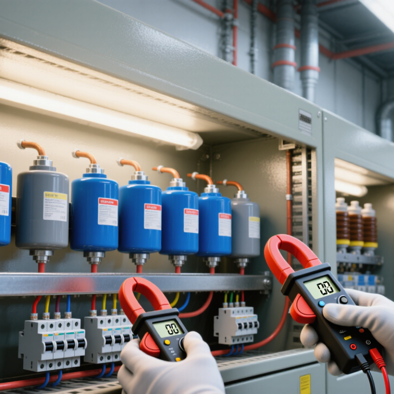
Compensation Capacitors help electrical systems manage reactive power, voltage stability, and energy efficiency. They are installed in power-factor correction circuits, motor-control panels, filters, and switching converters. Their purpose is practical: reduce unnecessary current without changing the useful load power.
Dr. Robert W. Erickson, a respected power-electronics authority, describes the basic principle clearly: “A capacitor is a device that stores energy in an electric field.” That stored energy can return to the circuit when needed. In an industrial panel, this may reduce the current flowing through cables and transformers. Lower current can also reduce copper losses and release capacity in distribution equipment. Small details matter. A capacitor’s voltage rating, tolerance, ripple current, and temperature rating all influence reliability.
The design is not simply a matter of adding capacitance. Poorly selected Compensation Capacitors may interact with harmonics, create resonance, or experience damaging inrush current. The result can be unexpected noise, overheating, or premature failure. This is where engineering judgment becomes essential. Measurements should include power factor, harmonic distortion, operating temperature, and transient behavior. A simplified calculation may look convincing. It may still miss the real problem.
Experience shows that capacitor selection must match the complete electrical environment. Engineers should examine load changes, switching frequency, protection methods, and maintenance conditions. The best solution is not always the largest capacitor. It is the correctly rated component, tested under realistic conditions, and monitored over time.
What Are Compensation Capacitors?
Compensation capacitors are small components that shape a circuit’s frequency response. They are commonly placed around amplifiers, regulators, and feedback networks. Their main job is stability. A capacitor adds a controlled phase shift, reducing unwanted oscillation when the circuit reacts to changing loads.
In an operational amplifier, the capacitor can create a dominant pole. This lowers high-frequency gain before parasitic delays become dangerous. The result is usually cleaner feedback and fewer ringing edges.
In power supplies, compensation networks also influence loop speed, transient response, and settling time. A poorly selected value may make the output slow, noisy, or unstable. Bigger is not always safer.
The IEEE 2023 review literature on voltage-regulator control commonly evaluates settling times below several hundred microseconds, although results depend heavily on topology and load conditions. Meanwhile, IEC 61000-3-2 limits harmonic current emissions for many equipment classes, encouraging careful power-stage and control design. Industry market assessments, including the 2024 capacitor outlook from Fortune Business Insights, indicate continued growth in capacitor demand as electronics become more power-dense. That trend increases the importance of accurate compensation.
Engineers often begin with a target crossover frequency, then verify gain margin and phase margin through simulation and laboratory testing. Real capacitors add tolerance, leakage, and temperature drift. My practical concern is simple: a simulated loop can look perfect, yet fail with a long cable or a different load. Measurement still matters.
How Compensation Capacitors Correct Circuit Imbalances
Compensation capacitors are used to correct timing, phase, and voltage imbalances inside electrical circuits. In an inductive load, current may lag behind voltage because magnetic fields consume reactive power. A properly selected capacitor supplies part of that reactive demand locally. The result can be a better power factor, lower line current, and reduced voltage drop across cables. The improvement is measurable with a power-quality meter, not judged by appearance.
In amplifiers and control circuits, the capacitor has a different task. It can slow a high-frequency signal, reduce unwanted gain, and keep feedback from producing oscillation. For example, a small capacitor across a feedback resistor may make an output waveform steadier instead of letting it ring after a sudden input change. Placement matters. Wiring resistance, stray capacitance, temperature, and operating frequency can change the result. A value that works at 1 kHz may create excessive delay at 100 kHz. The first calculation is rarely perfect. Engineers usually compare predicted behavior with oscilloscope traces, then adjust the value carefully. Too little compensation leaves instability; too much can make the circuit sluggish. That trade-off is easy to overlook.
Where Compensation Capacitors Are Used
Compensation capacitors are used wherever a feedback circuit needs better stability. They are common in operational amplifier circuits, voltage regulators, power converters, and motor-control systems. Their main job is to shape the circuit’s frequency response. This helps prevent unwanted oscillation, ringing, or sudden output changes.
In an amplifier, a compensation capacitor may connect between gain stages or across a feedback resistor. This creates a controlled delay and improves the phase margin. In linear regulators, it can work with the output capacitor to keep the feedback loop stable during load changes. Switch-mode power supplies often use compensation networks near the controller’s feedback pins. These networks help the converter respond when the input voltage or load current changes.
Physical layout matters. A long trace can add inductance, while a high-ESR capacitor can change the expected response. During bench testing, engineers often check the output with an oscilloscope after switching from light load to heavy load. A small burst of ringing may reveal poor compensation. Too much capacitance can also make the circuit slow. That trade-off is easy to underestimate. Designers should confirm the capacitor value across temperature, tolerance, and operating conditions. Simulation helps, but real measurements remain necessary. A circuit that looks stable on paper may behave differently with wiring, component aging, or an unexpected load.
How to Select the Right Compensation Capacitor
Why Are Compensation Capacitors Used?
Compensation capacitors reduce reactive power in AC systems and improve power factor. They can lower current, release transformer capacity, and reduce avoidable energy losses. However, choosing one is not a simple matter of matching capacitance values.
How to Select the Right Compensation Capacitor
Start with the system voltage, frequency, and measured power factor. A capacitor rated too close to the operating voltage may fail during normal fluctuations. Use the required reactive power to estimate capacitance: C = Q divided by 2πfV² for a single-phase system. Three-phase calculations need the correct connection arrangement. Check the actual wiring diagram.
The load profile matters greatly. Motors, welders, and variable-speed drives can create changing demand or harmonic currents. A fixed capacitor may overcorrect during light-load periods. Automatic steps are often more suitable for uneven loads. Choose voltage ratings with practical margin, then verify capacitance tolerance, temperature range, ripple current, and expected service life. Film capacitors are common, but construction and protection features still require inspection. Look for discharge resistors, pressure-interruption protection, and suitable enclosure conditions.
Do not select by capacitance alone. Measure the installation under real operating conditions, including startup events and peak load changes. I have seen acceptable calculations produce poor results when harmonics were ignored. That mistake is easy to repeat. A prototype test, thermal check, and follow-up power-factor measurement can reveal problems before full installation. Ageing also changes performance, so maintenance records should include temperature, current, swelling, and connection condition.
What Happens Without Proper Compensation?
A compensation capacitor controls how an amplifier or regulator responds across frequency. It helps preserve phase margin and prevents unwanted oscillation. Without proper compensation, a circuit may appear stable during a quick test, then fail under real operating conditions.
The warning signs can be surprisingly physical. An output voltage may show small ripples on an oscilloscope. A cooling fan might change speed repeatedly. Sensitive loads can reset when current demand changes suddenly. In one bench test, a circuit looked correct with no load, but produced a sharp ringing pulse when a motor started. The capacitor value was not the only issue. Its position, wiring length, and interaction with other capacitors also mattered.
Poor compensation can create excessive overshoot, slow settling, audible noise, or unexpected heat. In severe cases, the feedback loop continuously chases its own error. It becomes unstable. Designers usually check gain crossover, phase margin, load range, and temperature variation. Simulations help, but measurements still matter. Real circuit layouts often reveal parasitic resistance and inductance that models miss. I once treated a compensation capacitor as a simple add-on. That assumption was too narrow. A small value change improved one load condition but weakened another. Testing several operating points is safer than trusting a single waveform. The circuit may work today. Its behavior can still shift after component tolerances, aging, or a different power source.
Why Are Compensation Capacitors Used?
Compensation capacitors reduce reactive power demand and improve power factor. The chart shows the calculated line current for a balanced 100 kW, 400 V, 50 Hz three-phase load before and after correction to a 0.95 power factor.
Without proper compensation, a lower power factor causes higher line current for the same useful power output. This increases cable and transformer losses, voltage drop, and equipment loading. For the 0.70 power-factor case, correction to 0.95 requires approximately 102 kVAr of capacitive compensation and reduces current by about 26%.


Fabricator
Inside Sales and Client Support Manager
Glass Handler – 1st Shift