Taking Custom Design to New Levels
PROUD TO BE PART OF THE BRIN FAMILY OF COMPANIES

OTHER BRIN LOCATIONS
Brin Glass Company | Minneapolis, MN
St. Germain’s Glass | Duluth, MN
Heartland Glass | Waite Park, MN

A Thermal Expansion Vessel is a pressure-control component used in sealed heating and hot-water systems. It absorbs the extra volume created when water warms and expands. Without this buffer, system pressure can rise sharply. That pressure may trigger a relief valve or stress pipes, joints, and equipment.
Small vessel, major role.
Inside the vessel, a flexible diaphragm separates system water from compressed air or nitrogen. As heated water expands, the diaphragm moves into the gas chamber. This action helps maintain safer, steadier pressure. In practice, installation quality matters as much as the vessel itself. A heating technician may check the pre-charge pressure, system temperature, vessel position, and connection condition before commissioning. These details are easy to overlook.
The correct size depends on system volume, operating temperature, maximum pressure, and the vessel’s usable acceptance capacity. Manufacturer data should guide the final selection. A vessel that looks large enough may still be unsuitable. The label can mislead.
It is also important to distinguish a heating expansion vessel from one designed for potable water. Their materials, approvals, and operating conditions may differ. Local codes and professional guidance should always be considered. Regular inspection can reveal corrosion, pressure loss, or a damaged diaphragm before performance declines. Still, no vessel lasts forever. Even experienced installers can miss changing pressure conditions after a system is modified.
Understanding this component makes troubleshooting more practical. It connects pressure readings with real movement inside the system. That connection is the foundation for safer design, accurate maintenance, and informed equipment replacement.
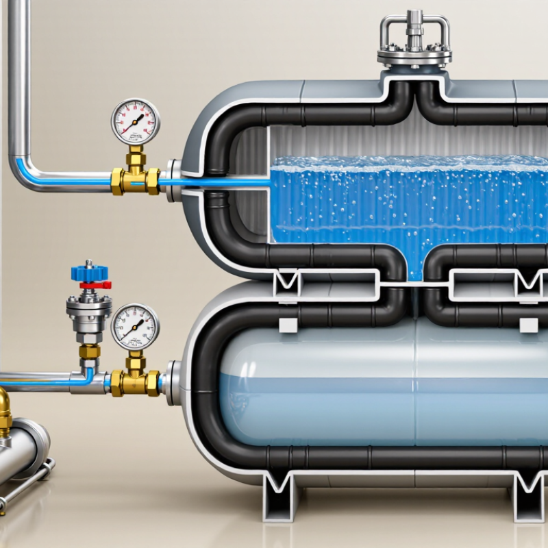
A thermal expansion vessel is a pressure-control component used in sealed heating and hot-water systems. Its purpose is to absorb water expansion as temperature rises. Water barely compresses, so heated water needs somewhere to move. Without that space, system pressure can increase sharply.
The vessel usually contains an air or nitrogen cushion separated from the water by a flexible diaphragm. As water expands, the diaphragm moves against the cushion. This action helps reduce pressure spikes, dripping relief valves, and stress on pipes, fittings, and heating equipment.
In practice, the vessel must match the system’s water volume, operating temperature, and pressure range. Sizing is not always obvious. An undersized vessel may appear normal during cold checks but struggle when the system reaches full temperature. That detail is easy to miss.
Tips: Check the vessel’s pre-charge when the water side is depressurized. Look for corrosion, damaged connections, or repeated pressure changes. A pressure gauge can reveal useful clues, but it cannot confirm diaphragm condition. Have a qualified heating professional test or replace the vessel when needed. Manufacturers’ specifications and local installation rules should guide the work. Small assumptions can create expensive problems.
What Is a Thermal Expansion Vessel?
A thermal expansion vessel is a small pressure-control tank used in closed water systems. It is common in heating circuits and domestic hot-water installations. When water heats, it expands and needs somewhere to move. Without controlled space, pressure can rise quickly inside pipes, heaters, and valves.
How Thermal Expansion Vessels Work
Inside the vessel, a flexible diaphragm separates system water from compressed air or nitrogen. As heated water expands, it enters the vessel and pushes against the diaphragm. The gas compresses, absorbing the extra volume. When the water cools, the stored pressure helps return water to the system.
The vessel must have the correct pre-charge pressure. A technician checks this setting with the water side depressurized, then compares it with the system’s operating pressure. A wrong setting can cause frequent pressure changes or premature component wear. Small vessels may look harmless. They are not.
A relief valve remains essential because no vessel can handle every fault condition. If pressure keeps rising, the vessel may be undersized, waterlogged, or isolated by a closed valve. That explanation is useful, but incomplete. Expansion vessels can lose pressure over time, even when no leak is visible. Regular inspection should include the air charge, connections, corrosion, and relief-valve discharge pipe. Installation details vary by system design, so a qualified professional should verify the vessel’s size and position.
A thermal expansion vessel manages pressure changes in a sealed water system. As water heats, it expands and needs somewhere to move. Without that space, pressure can rise sharply and stress pipes, valves, and heating equipment.
Its steel shell contains a flexible diaphragm or bladder. One side holds system water, while the other side contains compressed air or nitrogen. A water connection links the vessel to the pipework. A gas valve adjusts the pre-charge pressure, but this setting must match the system design. A pressure gauge can help during checks, although it does not replace proper testing. Small details matter here.
Common vessel types include fixed-diaphragm, replaceable-bladder, potable-water, heating, and solar-system models. Fixed-diaphragm vessels are compact and often economical. Replaceable-bladder designs may simplify maintenance when the membrane wears. Potable-water vessels require suitable internal materials. Solar vessels need components that tolerate higher temperatures and more demanding fluid conditions. Selection depends on water volume, temperature range, operating pressure, and installation position.
Sizing is not always neat. A vessel that looks large enough may still lose pressure control if its pre-charge is wrong. Inspectors should check corrosion, leakage, connection condition, and membrane performance. The vessel should be isolated safely before testing. In practice, many failures begin with an overlooked pressure setting, not a dramatic manufacturing defect.
A thermal expansion vessel is a sealed tank installed in a closed, pressurized water system. It contains water on one side and compressed air or nitrogen on the other. As water heats, it expands. The vessel absorbs this extra volume and helps control pressure changes. Without it, pressure may rise sharply near a boiler, water heater, or heat exchanger.
These vessels are commonly used in domestic hot water systems. You may find one beside a storage cylinder, often connected to the cold-water line. They are also used in closed-loop central heating systems, where heated water circulates through radiators or underfloor pipes. Solar thermal systems need them too, because fluid temperatures can change quickly under strong sunlight. In commercial buildings, larger vessels support chilled-water circuits, industrial heating loops, and some process-water systems.
Installation details matter. The vessel should suit the system volume, operating temperature, and maximum working pressure. Its air charge must match the design conditions, and a pressure gauge should be checked during commissioning. In real maintenance work, sizing is sometimes treated as an afterthought. That can lead to frequent relief-valve discharge or unstable pressure. The vessel also needs inspection for corrosion, membrane damage, and lost pre-charge. A small tank may look sufficient, yet perform poorly when demand changes. Pressure readings can be misleading if the system is still hot. Testing it under the wrong conditions is an easy mistake.
What Is a Thermal Expansion Vessel? Sizing, Installation, and Maintenance Considerations
A thermal expansion vessel absorbs pressure changes in sealed heating and water systems. Water expands when heated, but it cannot compress inside fixed pipework. NIST water-property data shows expansion of about 2.9% between 10°C and 80°C. A 100-litre system therefore gains nearly 2.9 litres. That volume needs controlled space.
Sizing requires more than matching the vessel to system volume. Calculate the heated water expansion, then divide it by the vessel’s usable acceptance factor. ASHRAE Handbook—Fundamentals provides temperature and density data for this calculation. Static height also matters. A taller building needs higher cold-fill pressure. Many systems set pre-charge near static pressure, with a small engineering margin. Always verify the vessel’s pressure curve and local code requirements. A neat spreadsheet is not enough.
Installation affects performance. Connect the vessel to the system’s pressure-stable point, commonly near the pump inlet. Keep the connection short and free from blockage. Install an accessible isolation valve only where regulations permit it. During commissioning, check pre-charge with the water side depressurised. Otherwise, the reading can mislead you. Maintenance should include annual pressure checks, visual inspection, and relief-valve testing by qualified personnel. Loss of air charge often appears as rapidly rising pressure, dripping discharge, or frequent topping-up. These symptoms deserve investigation, not just another refill. The calculation may still need a second look.
| Data Dimension | Typical Data or Requirement | Practical Consideration |
|---|---|---|
| Primary Function | Absorbs the increase in water volume caused by heating in a closed-loop plumbing or hydronic heating system. | The vessel helps limit pressure fluctuations and reduces discharge through the pressure-relief valve. |
| Common Applications | Closed-loop hydronic heating, chilled-water systems, domestic hot-water systems, solar thermal systems, and process-water circuits. | The vessel must be approved and rated for the specific fluid, temperature, pressure, and installation environment. |
| Construction | A sealed steel tank divided by a flexible diaphragm or bladder into a water side and a pre-charged gas side. | The diaphragm or bladder prevents direct contact between the system water and the gas charge in standard designs. |
| Water Expansion | Water expands as temperature rises. Between approximately 10°C and 80°C, water volume increases by about 2.9%. | The required vessel size depends on the total system water volume and the operating temperature range. |
| Key Sizing Inputs | Total system water volume, minimum system temperature, maximum operating temperature, initial fill pressure, maximum allowable pressure, and vessel pre-charge. | A larger system volume or wider temperature range generally requires a larger vessel. |
| Basic Expansion Calculation | Expansion volume = system water volume × water-volume expansion fraction. | For example, 300 L of water heated from 10°C to 80°C expands by approximately 8.7 L before vessel pressure effects are considered. |
| Illustrative Vessel Estimate | For a 300 L hydronic system with an approximately 8.7 L expansion volume, a vessel nominally around 18–25 L may be required, depending on pressure settings and the manufacturer’s sizing method. | This is an illustrative range, not a final selection. Confirm the result using the vessel manufacturer’s technical data and local code requirements. |
| Typical Pre-Charge Setting | Often set near the required cold fill pressure, commonly about 1.0–1.5 bar in small closed hydronic systems. | The exact setting depends on building height, static pressure, system design, and the vessel manufacturer’s instructions. |
| Cold Fill Pressure | A common design approach is to maintain sufficient pressure at the highest point, often adding approximately 0.3 bar safety margin above the static head requirement. | Do not exceed the rating of the lowest-pressure component in the system. |
| Maximum Working Pressure | Common vessel ratings include approximately 3 bar, 6 bar, 8 bar, or 10 bar, depending on the application and design. | The vessel rating must be equal to or greater than the system’s maximum allowable working pressure. |
| Maximum Temperature | Heating-system vessels are commonly designed for water temperatures around 90°C to 120°C, while potable-water vessels may have different limits. | Always verify the vessel’s temperature rating, especially in solar thermal and high-temperature heating systems. |
| Installation Location | Install on the system side where pressure changes need to be controlled, commonly near the boiler, heat source, water heater, or pump connection point. | Follow the approved system layout and allow sufficient clearance for inspection, replacement, and service access. |
| Connection Orientation | Many vessels can be installed vertically or horizontally when properly supported, but the permitted orientation depends on the design. | Use a support bracket or suitable mounting method. Do not allow unsupported pipework to carry the vessel’s full weight. |
| Isolation and Drainage | A service isolation valve and a means of safely draining or depressurizing the vessel are recommended where permitted by the system design. | The isolation arrangement must not compromise the function of the pressure-relief system. |
| Pressure-Relief Protection | A correctly sized and rated pressure-relief valve is required to protect the closed system from overpressure. | Never block, cap, or isolate a pressure-relief valve from the system unless an approved equivalent safety arrangement is provided. |
| Pre-Charge Inspection | Measure gas pre-charge with the water side fully depressurized and isolated from system pressure. | Measuring pre-charge while the vessel is pressurized with water produces an unreliable reading. |
| Recommended Maintenance Interval | Inspect at least annually; commercial, high-temperature, or critical systems may require more frequent checks. | Record pressure readings, leakage observations, relief-valve activity, and any changes in system pressure. |
| Common Failure Signs | Frequent pressure-relief discharge, rapidly changing pressure, repeated need for system top-up, water at the gas valve, corrosion, or unusual noise. | Water escaping from the air valve may indicate a failed diaphragm or bladder and usually requires vessel replacement. |
| Replacement Criteria | Replace the vessel if the diaphragm or bladder has failed, the shell is corroded or damaged, the vessel cannot hold its pre-charge, or its pressure rating is unsuitable. | Select a replacement with compatible volume, connection size, pressure rating, temperature rating, and fluid approval. |
| Safety Requirement | Installation, testing, and servicing should be carried out by a qualified professional in accordance with applicable plumbing, heating, pressure-equipment, and building regulations. | Fully isolate, cool, drain, and depressurize the system before servicing the vessel. |
Taking Custom Design to New Levels

Brin Glass Company | Minneapolis, MN
St. Germain’s Glass | Duluth, MN
Heartland Glass | Waite Park, MN

Fabricator
Inside Sales and Client Support Manager
Glass Handler – 1st Shift